|
|
|
|
中文版 | News | Archives | Reviews | Forum | $ Deals | Links | History | Contact | Privacy |
|
| ||||
|
THE MULTI MOD GUIDE Updated 05/11/02 by Tim B @ OCWorkbench.com The Original Guide by
Kevin Cribbs. The Updated Method by
Iggy. Useful related pages. Sources for parts Images of solder locations
courtesy of Jinxter. More pics and info can be
found here courtesy of Miikka Kolo By Iggy. For everyone that want to make multi mod, and doesn't want to touch their cpu...apart from unlocking it! This is nothing new. You can read original Kevin Cribbs artical here Be sure to understand it completely, and go to the links he provided to learn more, as I don't want to repeat everything there said. My thanks go to Kevin Cribbs for doing the mod and the explanation in the first place, and to Pegelius, who made more mods and pictures available to all of us to use... Doing this mod will void your warranty for the MoBo, and I will not be held responsible for any mistake made in this article or failure that may occur after it has been carried out. I checked the article thoroughly, and beleive the info to be accurate. I'm using 2 dip switches. One is for choosing FID0-3, and it is ordinary 4-way dip switch, and other one is tri-state dip switch for choosing BP_FID0-4. The reason for using
tri-state dip swithces is that there is no danger of shorting Vcore &
ground, as the switch has three positions: first connects the BP_FID to GND, second
(middle) leaves it open, and third connects it to Vcore.
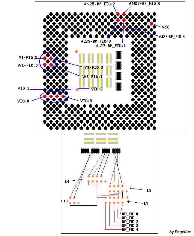
This is the schematic of the mod. It is neccessary to be sure that, when switches in the tri-state dip switch are down, they must make connection with Vcore. (***) Thats why it is wise to understand how this switch work using Ohm meter (or DMM). Three switches have been left unconnected for the convenience.
This image shows that you need to cut the traces at the bottom of the board that connect FID pins with the transistor on the top of the board. It is neccessary for proper working of the modification. It is not an exact representation of the traces. It is possible to make the cuts on the traces apart from each other, in order to be able to connect them later on. The traces are grouped together (4 of them), and it shouldn't be difficult to find them. A check can always be made with DMM to assure the cutting has been succesfull (sharp knife will do, and don't go too deep). The next image will show where you can find FID and BP_FID pins:
I have to thank Pegelius for allowing me to make a direct link to his pic. BP_FID4 is used to access multipliers above 12.5. That's about the mod. I leave soldering and thinkering how to connect the wires to you. Don't make the wires too long. As for the changing of the multi, it is important that FID and BP_FID are switched in same direction. So, If FID switch is down, the corrensponding BP_FID will be down, as well. (Refer to ***). If BP_FID4 is down, it will switch on multis from 13 onwards, using FID0-3 and BP_FID0-3, and using translation table in which multi of 5.0 is actually 13, and so on. (Only for AXPs/Morgans, but may work with T-Brids/S-Fires) If all is OK, I think these are the right positions of the switches for the corrensponding multis: multi, FID0-3 05.0 u u d u U=up, d=down The modification is quite easy. Take your time when doing it, and often use DMM to check on the contacts and soldering done. If carefully done, it will work from the start. I must say that it is important to UNLOCK your cpu. There are many posts on that matter on this site. The mod works for Durons (Spitfires and Morgans) and for Athlons (Thunderbirds and XPs). As soon as the multi has changed, the Bios will revert booting FSB to 100. LATEST: If you have AXP/Morgan, it is possible to make Multi-Lite mod. It comprises of tri-state switch only, no FID switch is req'd, and there is no need to cut any of the FID traces. Multi will change according to the table above. GND can be taken from underneath USB/Parallel/Serial/Mouse/Keyb ports. If you want to know REAL Vcore voltage, it can be measured directly on the tri-state switch (MoBo gives slighly lower value). For the understanding of how multiplier adjustment work, check this web page Instead of using tri-state dip switch, it is also possible to use jumpers, slide switches or rocker switches (two position, three contacts), connecting them as shown on the small drawing on the right of multi-mod schematics. Iggy...
|
|
(C) Copyright 1998-2009 OCWorkbench.com
|