|
|
|
|
中文版 | News | Archives | Reviews | Forum | $ Deals | Links | History | Contact | Privacy |
|
| ||||
|
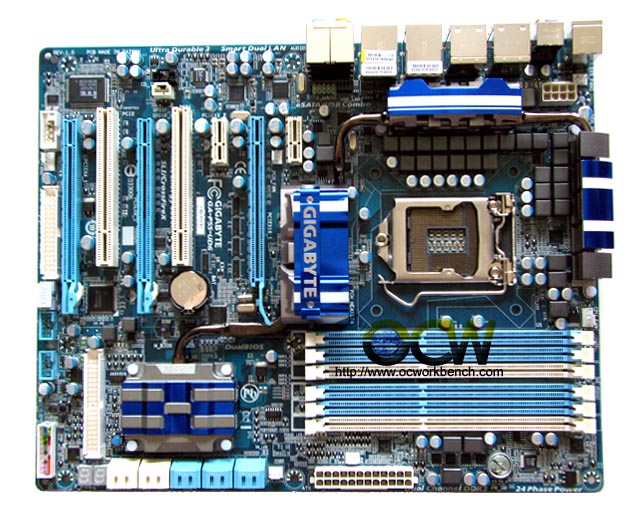
Mainboard Layout of Gigabyte GA-P55-UD6 Intel P55 Lynnfield
Mainboard Gallery
The Gigabyte P55-UD6 ATX mainboard comes with 3 full length PCe slot which can be used to run 2 or 3 way SLI or CrossFire. Behind the orange slots are the Audio codec, GbE and IO controller chip. To the right is the 24 power phase with a heatpipe attached on top. Surrounding it is the LGA1156 socket which fits Core i7/i5 Lynnfield processor. Behind the blue PCIe slots are the I/O controller chip, audio codec and Dual LAN chip. Right below is the DIMM slots supporting up to 24GB of DDR3 modules. This is unusual as most boards only comes with 4 dimm slots. Just right below the DIMM slot is the Power On button.At the centre of the board is the P55 single chipset. The connected heatpipe heads south and covers two SATA2 chipset, both from Jmicron (one labelled Gigabyte). Both supports 2 SATA2 ports. So, we have a total of 10 SATA 2 ports on this board. To the left of the white SATA2 slot is the DEBUG LED. the IDE port, front panel connector, external USB brakcet, 1394 controller chipset are right below the PCI white slot.
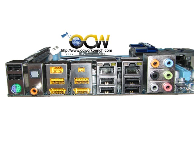
The back panel consists of PS/2 keyboard/mouse port, 8 USB ports, 2 Powered eSATA+USB combo ports, 2x1394 port, 2 GbE, SPDIF analog and digital out, and audio ports.
Next >>>
|
|
(C) Copyright 1998-2010 OCWorkbench.com
|