|
|
|
|
中文版 | News | Archives | Reviews | Forum | $ Deals | Links | History | Contact | Privacy |
|
| ||||
|
THE VCORE MOD GUIDE Updated 05/11/02 by Tim B @ OCWorkbench.com The original guide by
Kevin Cribbs Variable Resistor Guide
by Ezra Useful Related Threads -
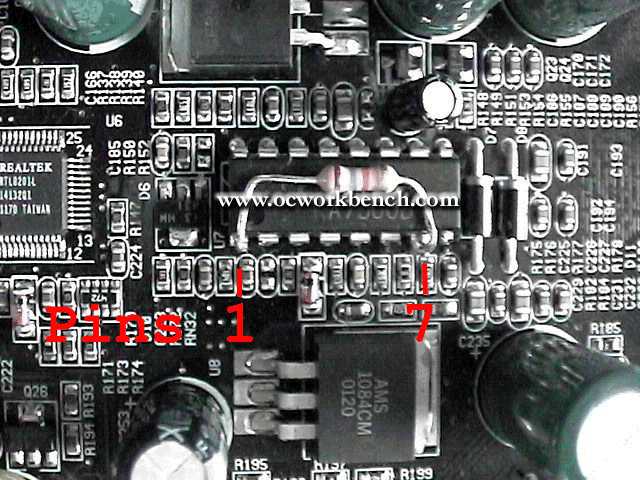
highly recommended read. NOTE: Less resistance = higher vcore!, check the potentiometers variable resistance before turning the power on to ensure its at the right end of the scale. By Ezra. I had a good look at this picture from Mr. Cribbs's article:
The chip in the picture is near the CPU and the AMR slot. I went over to Radio Shack (a US chain of electronics stores) and bought a small 47k-Ohm potentiometer (variable resistor) that is "suitable to be mounted on a printed circuit board". I also got hold of a couple tiny clips with 8" (20 cm) leads. Total cost, including tax, was less than 2 USD. The object of the game here, for those that don't know, is to use a resistor to bleed off a little current from the voltage regulator so that it will raise Vcore to compensate. Since we want to keep Vcore as low as possible--don't want to fry the Duron!--while still achieving the desired clock speed, we need a way to adjust the resistance. So we use an adjustable resistor (the potentiometer) and twiddle it until we get what we want. Anyway, I soldered the lead from one clip to the center leg of the potentiometer and the lead from the other clip to one of the other legs (it doesn't matter which). I wrapped the potentiometer in electrician's tape, insulating the solder points but leaving the little dial exposed so I could adjust it. I turned the dial clockwise as far as it would go and measured the resistance from one clip to the other with my multimeter, getting a reading of 44.0k-Ohm. Since Mr. Cribbs had expressed some concern that using a potentiometer in this application could introduce unknown capacitance or inductance into the system, I also used my multimeter to measure the capacitance of my device. The capacitance was below the minimum that my multimeter could measure, 0.002nf. I assumed that a stray 2pf is too small to have an effect on the K7S5A. I do not have the means to measure inductance, so I resolved to keep the leads nice and straight. Next I referred to the picture above and clipped one lead to pin 1 and the other to pin 7 of the voltage regulator chip. Noting that the tiny clips didn't grip the pins of the chip very firmly, I used a little electrician's tape to keep everything in place. I then turned on the machine. Success! Well, it powered on and started to POST, anyway. I hit Del and proceeded to the BOIS hardware monitor to look upon what I had wrought. It was good. Vcore was reading 1.640v, up from 1.600v. Everything else looked as stable as ever. Since I had already tried pencilling the L7 bridges without success, I knew to dial the potentiometer so that Vcore went above 1.840v, the highest Vcore I had achieved with my pencil. I dialed up 1.880v and tried to boot. The machine booted fine and I played around for about 15 minutes before it reset itself. Needless to say I hit Del again and went to the hardware monitor. After making sure that heat was not a problem (CPU temp was below 40C), I dialed the Vcore a little higher. I found that the smallest adjustment I could make was from 1.880v to 1.925v. Either the $0.79 potentiometer has some granularity so that a finer adjustment is not possible, or the K7S5A hardware monitor cannot resolve a smaller difference in Vcore. I booted anyway and gave it a try. This time I had REAL success! I ran the system under a normal load for an hour or so, noting that (thanks to my FOP38 and a tiny amount of Arctic Silver) CPU temp never exceeded 105F (41C). Then for load testing I played Tribes2 for an hour, noting much better performance and that CPU temp never exceeded 107F (42C). In my opinion a robust FPS game is in many ways a better system test than most benchmark software. The action is heavy and continuous, and all components of the system are used all the time, particularly with an on-line game like Tribes2. So for about $1.78 and an hour of pleasant work I made my computer 33% faster. (Many, many thanks to Kevin Cribbs for the article and photo, and to OCWorkBench for hosting it all. I hope no one minds that I swiped the picture.)
|
|
(C) Copyright 1998-2009 OCWorkbench.com
|