|
|
|
|
中文版 | News | Archives | Reviews | Forum | $ Deals | Links | History | Contact | Privacy |
|
| ||||
|
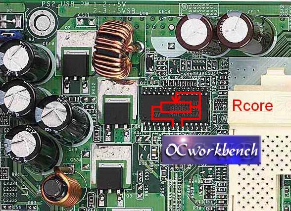
K7S8X Voltage mods All the mods described below were checked by myself, and worked as expected. Be careful! You are doing it at your own risk! Modding voids warranty! Vcore mod Vcore voltage regulator is a 2 phase design based on the L6917 by ST. The chip is located at the top of the pcb, left to the CPU socket. Vcore is defined by the state of the Vid input pins. Signals to these inputs come from the CPU itself. However there is another way of modifying Vcore voltage: by changing the feedback voltage of the regulator. The feedback input is located at pin9 of the L6917 and the feedback voltage is connected through a resistor going from the regulator output. The modification consists of soldering another resistor from pin 9 to GND to divide the feedback voltage wich results in increased output Vcore. The best way to do it is to solder a variable resistor 47k or 100k multipot between pin 9 and pin 7 of the L6917, as shown at the picture below. You can then adjust the desired Vcore voltage by trimming it with the pot while controlling it from the bios hardware monitor. Be sure to set the pot at its maximum value before soldering! Not doing this can result in too high Vcore and damage your CPU.
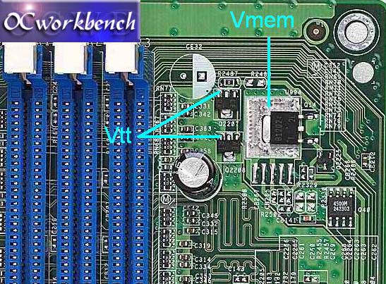
Vmem mod The theory: Memory uses 4 voltages (Vddq, Vdd, Vr, Vtt) that need to be in very close relationship to each other. Vdd and Vddq are memory power supplies, for internal electronics and output
buffers. They are feeded by the same voltage regulator, as they require the same
voltage, which we all refer to as Vmem, or Vdimm. It should be 2.5V +/- 0.2V for
DDR266 and DDR333, or 2.6V +/-0.1V for DDR400. Asrock choose to make it 2.7V. To
adjust this voltage resistor Rmem is needed.
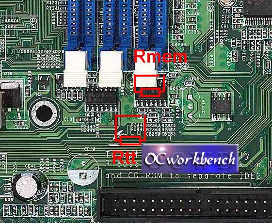
Below you can find resistor pairs calculated in such a way, that the memory voltages are within specs. Just solder them as shown at the picture below: resistor Rmem in parallel to R2370, and Rtt in place of R2449 (the resistor wasn't factory installed) Vmem=2.7V -> Asrock did it for you :-)
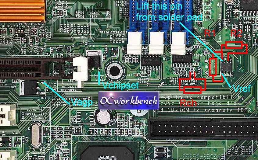
Vchipset mod Vchipset can be measured at the point indicated as Vchipset (see picture below) and is 1.8V by default. Vchipset regulator is made using the Q16 transistor and some of the op-amps from the two LM324 located under the memory slots. Vchipset. is determined by 2 resistors, R2368 (390) and R2369 (1k) and the
reference voltage comming from the LM431 chip. If you did the Vref mod, your
chipset voltage is already higher! Use the new Vref voltage in the equation
below! Below you can find resistor values already calculated for you: Vchipset=1.9V -> Rch=1.5k You can also solder a variable resistor 4.7k multipot and
adjust the desired value (measure at the Vchipset point).
Vref (Vmem, Vagp, Vchipset) mod There are 3 important voltage regs on the K7S8X: I further examined Q14, Q16 and Q18. All 3 regulators are made using 2 LM324 IC's (quad op-amps) and a voltage reference LM431 (all located under the memory slots). The easiest way to change all these voltages at once is to change the reference voltage. The reference voltage can be changed by adding 2 resistors around the reference LM431. Changing the voltage reference results in changing all 3 voltages - Vchipset, Vagp and Vmem! Be careful! The mod (see picture above): 1. Locate the LM 431 chip. - Vmem from 2.70V -> 2.87V |
|
(C) Copyright 1998-2009 OCWorkbench.com
|